What to photograph before concealing building services on site
A protocol to document ducts, trays, wiring, pipes, grooves, runners, passages and seals before placing false ceilings, plates, coverings or screeds. The objective is not to accumulate images: it is to be able to locate and understand later what will no longer be visible.
1. Prepare checkpoints before taking photos
Documentation begins before opening the camera. Review the work program and mark which areas will lose visibility: closure of false ceiling, placement of plates, plastering of paths, closure of slabs, pouring of screeds or installation of coverings. Each of these milestones must have a responsible person and a prior verification.
The photographic specification of the US Department of Veterans Affairs is a useful reference: ask for images indexed by time and location and taken at critical milestones, not an unstructured portfolio of photographs. The British Guide to golden thread It also insists on maintaining digital, usable, updated and accessible information as a source of truth for the building.
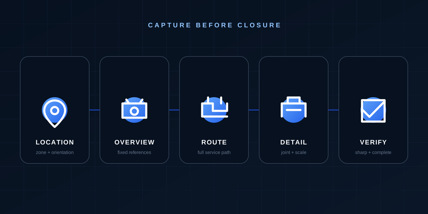
A coherent sequence preserves more context than several isolated photographs: location, set, route, detail and verification before closing.
Minimum checkpoint data
Project, floor, area or room and orientation of the camera.
System photographed: electrical, HVAC, plumbing, PCI, data, sanitation or other.
Status: installed, pending review, fixed or ready to close.
Date, author and reference to the plan, incident or related inspection.
Next action and responsible if something pending is detected.
2. Which areas and building services to photograph
Prioritize what will be expensive, destructive, or unsafe to rediscover. The list must be adapted to the project, but these are the families that usually lose visibility:
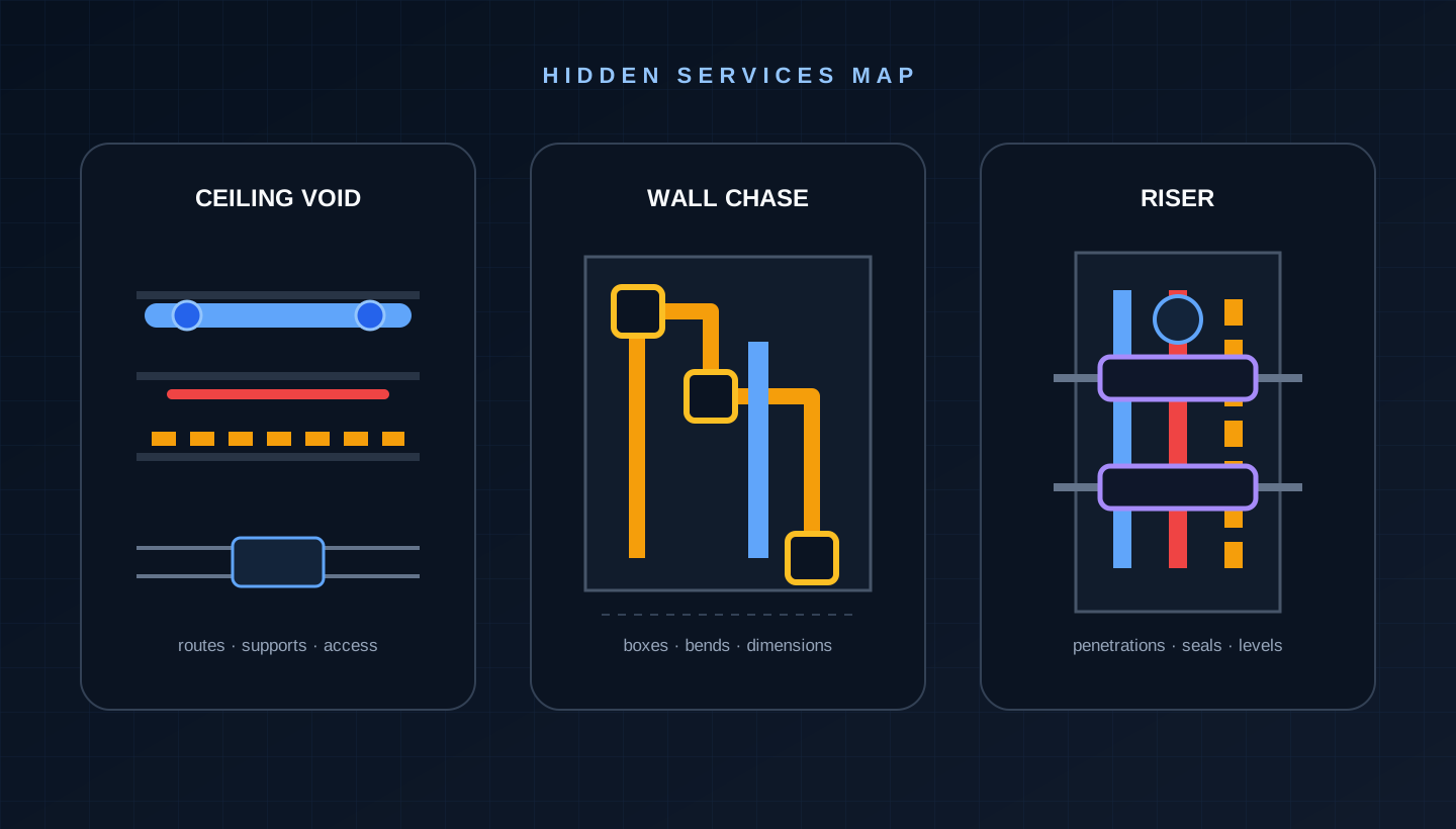
Three areas of high documentary value: false ceiling plenums, openings or backsplashes and vertical ledges. In all of them it is important to relate the route, meetings and accessible points.
About false ceilings: ducts, trays, pipes, sprinklers, gates, valves, junction boxes, supports and crossings between trades.
In slashes and transfers: electrical conduits, boxes, water pipes, drains, insulation, reinforcements and changes of direction.
On skates and uprights: routes across floors, clamps, joints, valves, manifolds, slab penetrations and access panels.
Under floors or screeds: tubes, pipes, underfloor heating, manholes, joints and distance from fixed references.
On walls and slabs: cable, pipe and conduit penetrations; sleeves, seals and edge protection.
In technical rooms: connections to equipment, circuit identification, maintenance access, drains and cutting elements.
3. Suspended ceilings: documenting ducts, cable trays and pipes
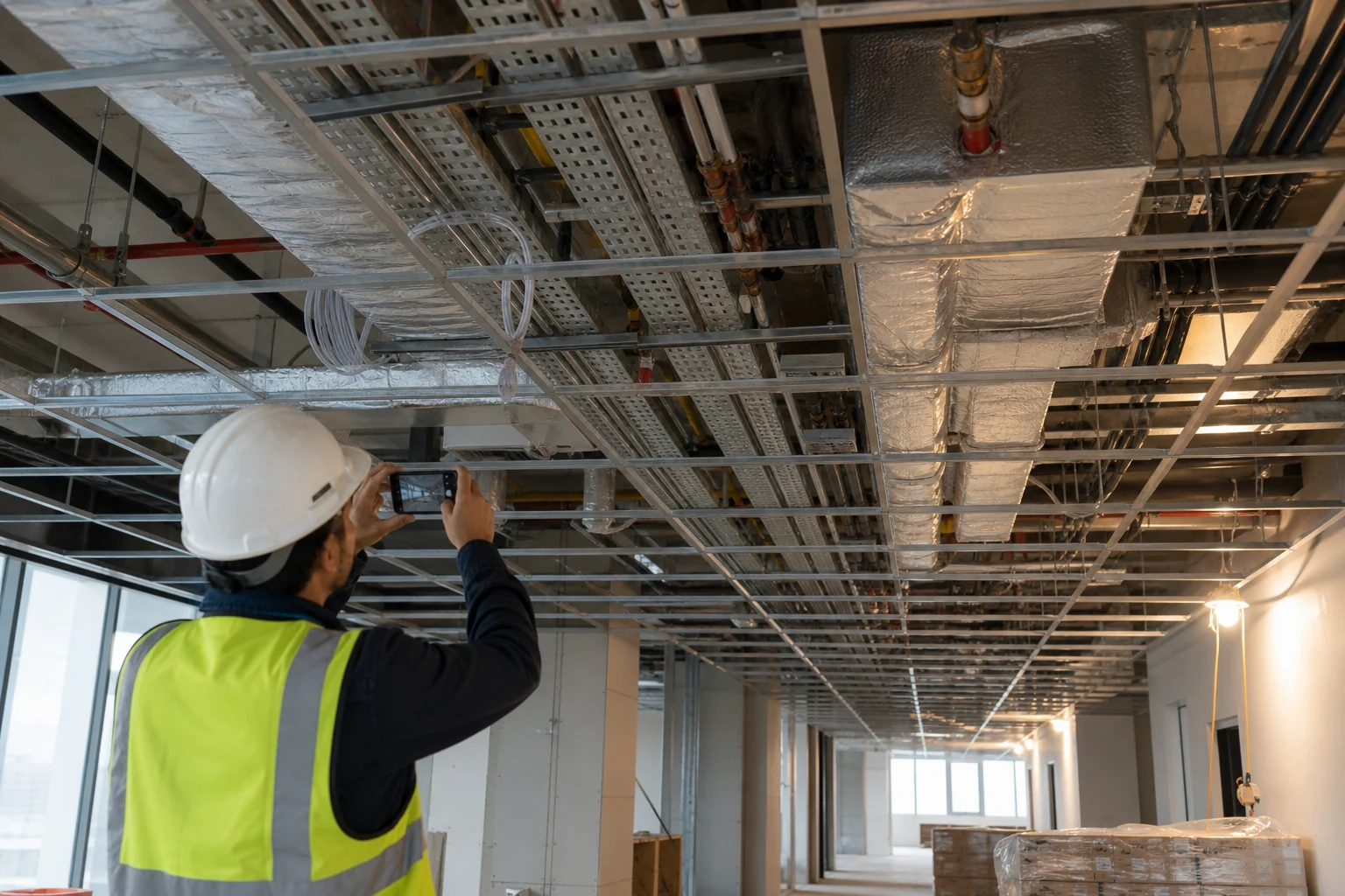
Do not photograph the plenum as a mass of installations. Divide the route into recognizable sections and maintain overlap between images. Start from a door, pillar, façade, pavement change or axis that allows the position to be recognized. Then follow each system to its branch or equipment.
Editorial photography generated to illustrate correct timing: visible installations, roof references and capture from a safe position before placing the plates.
Recommended captures
General view of the room with part of the grid, walls and gaps visible.
Longitudinal route of ducts, trays and pipes with one image per section and sufficient overlap.
Congested junctions between HVAC, electrical, PCI, plumbing and structure.
Fire dampers, valves, boxes and elements that require registration or maintenance.
Supports, hangers, insulation, flexible joints, slopes and connections to terminals.
Planned position of roof registers and approximate distance to the accessible element.
4. Wall chases, partitions and linings: record the entire route
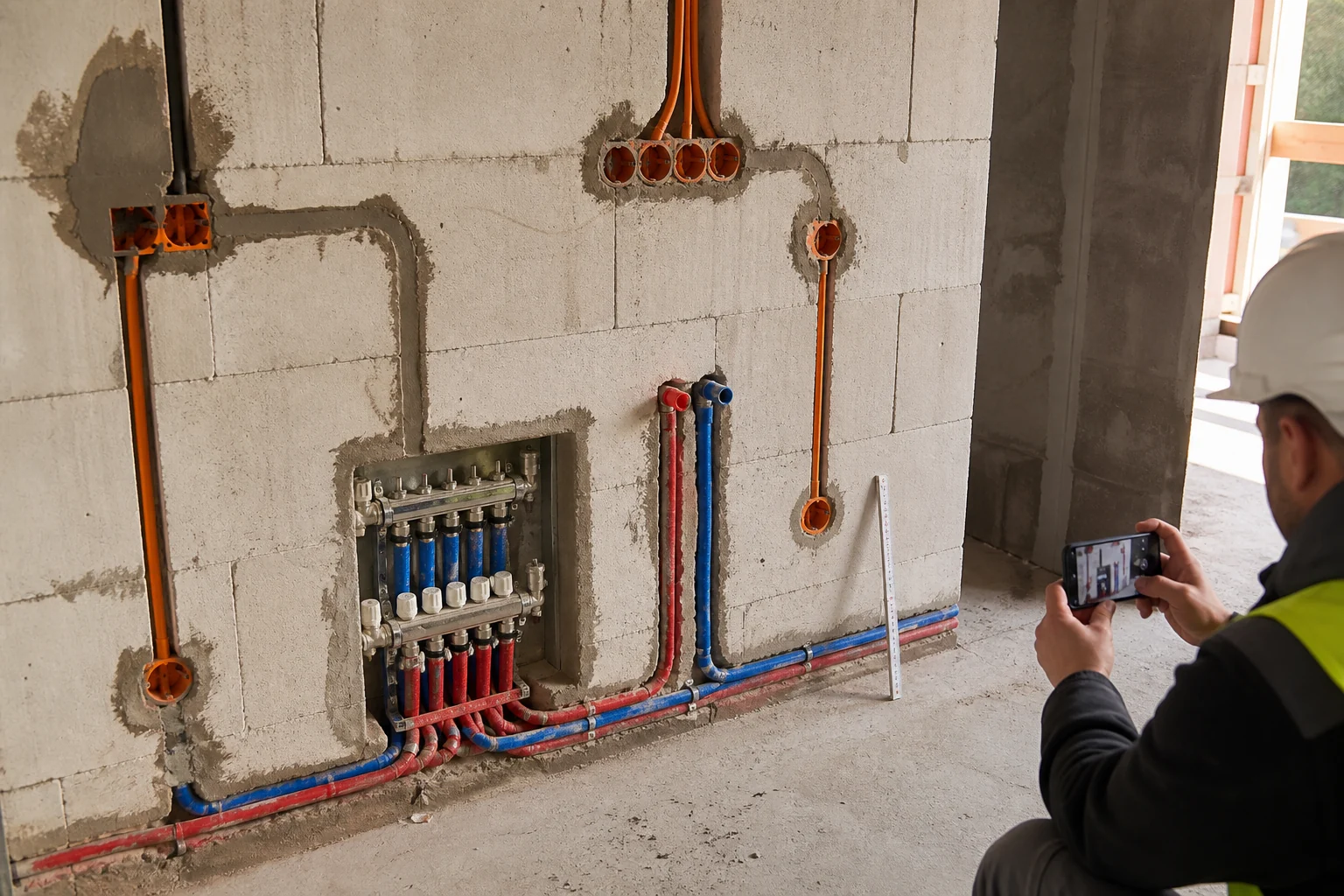
On one wall, a close-up photo of a box doesn't explain where the tubes go. Capture the entire surface first and then the sections. Includes corners, steps between rooms and any transition between a walkway, a lining chamber and a false ceiling.
Editorial photograph generated to illustrate a capture in rozas. The ruler adds scale to the detail, but the view maintains enough wall and gaps to identify the location. The reference should never cover the documented element.
Photograph each complete panel before plastering, backing or placing the second side of the plate.
Includes boxes, tubes, pipes, collectors, supports, reinforcements and ends pending connection.
Records changes of direction, groupings, separations and crossings between systems.
When a measurement is relevant, place a ruler or reference without hiding the installation and also take a clean photo without it.
Repeat the capture after correcting an issue; do not leave as the last evidence a condition that no longer exists.
For electrical installations, the photo helps to recover the route, but it does not in itself prove the safety of the installation. The Approved Document P, for example, clearly separates design, installation, inspection, testing and delivery of information.
5. Service risers, penetrations and seals: photograph before and after
In wall or slab steps it is not enough to see that “there is a tube”. The documentation must relate the through element, the support passed through, the sealing solution and its final state. Photograph the hole and the services before sealing and repeat the photograph once completed, with a visible label or reference if the system requires it.
The official British guide on fire safety reminds that gaps around cables and pipes can allow fire and smoke to pass through and pays special attention to walkways and meter cabinets. You can consult the section penetrations and compartmentalization on GOV.UK. As an example of a documentary protocol, the manual Hilti CFS-DM expressly distinguishes photographs before and after the installation of the sealing.
Plan or level view that identifies the patio.
Full view of the interior before closing it.
Each step of the floor or wall, including the edge of the opening.
Finished solution, label, product or documentary reference where applicable.
Valves, gates and registers with sufficient space to operate and maintain.
Important limit: A photograph can facilitate inspection and traceability, but it does not in itself demonstrate that a seal, a gate or an installation complies with the tested system, the project or the applicable regulations.
6. Five views that let you identify an installation later
There is no universal number of photos per stay. The correct amount is the minimum that preserves location, continuity and detail without leaving gaps. This table serves as a quality control:
Framing
What should you show?
Frequent error
Location
Room, axis, door, pillar, façade or recognizable reference.
Start directly with a close-up that is impossible to place.
Overview
The set of systems and their relationship with the geometry of space.
Frame so open that the facilities cannot be distinguished.
Tour
Continuity from origin to destination, with overlap between photographs.
Jumps between sections that make it impossible to reconstruct where it passes.
Detail
Derivation, union, box, valve, support, penetration or incidence.
Blurred, dark or unscaled photo when dimension matters.
Final state
Correction made, sealing completed or area ready to close.
Keep only the image of the defect prior to repair.
Before leaving the area, enlarge the images on the screen. Check focus, reflections, exposure and that the critical element is not covered by a hand, a ruler or work material. If a sequence is not understood at the time, it will be even more difficult to interpret it months later.
7. How to organize this protocol with Pic on Site
Pic on Site can convert the capture into a shared and searchable file, as long as the team maintains a consistent routine:
1. Define zones and milestones
Prepare the list of floors, rooms and planned closures. Do not wait for the office to announce the closure when it is already ending.
2. Capture one sequence per point
Maintain the order location, set, route and detail. If there is a fix, add the subsequent state in the same context.
3. Relate the image to the project
When the photo contains valid GPS, Pic on Site can help locate it. Indoors, always verify the position and rely on the plan, the area and visible references.
4. Check by date, author and content
Centralizing avoids depending on a person's mobile phone. Filters and search help gather relevant evidence before a review or intervention.
5. Close with a decision
Records whether the zone can be closed, what is missing, who must resolve it, and when the check will be repeated.
The area, plan and orientation can be recognized without depending on the photographer's memory.
There is an overview and the complete route appears without jumps.
Derivations, boxes, valves, supports, registers and direction changes have detail.
Passages through walls and floors are documented before and after sealing when applicable.
Images are in focus, correctly exposed and without obstacles in front of the element.
Corrected issues have a comparable after-photograph.
Date, author, zone, system, status and document reference can be retrieved.
Items that need maintenance will still be accessible from a planned registry.
The technical review, tests and required approvals are recorded separately.
9. Safety, privacy and the limits of photographic evidence
Do not change a safe route, remove protection, or approach edges, loads, or active equipment to achieve a frame. Coordinate capture with ongoing jobs and avoid interrupting the tradesman who is installing or testing the system.
Avoid faces, documents, screens, license plates or information unrelated to the technical purpose. An identifiable person and location data may be personal data; the European Commission summarizes when the GDPR applies. Defines purpose, access, conservation and dissemination rules for the file.
What a photo shows: a condition visible from a frame and at a specific moment. What it doesn't prove: what is left out of the field, internal behavior, the result of a test, complete regulatory compliance or contractual acceptance.
10. Frequently asked questions
When should photos be taken?
After completing and reviewing the installation, but before placing the element that will hide it. If something is corrected, repeat the sequence before final closure.
How many photos do you need?
There is no fixed figure. They should be enough to recognize location, route and critical details. Five useful images usually provide more than twenty repeated shots.
Can I trust the GPS inside the building?
Not always. Checks the position and maintains floor, area and orientation references. If the data is not valid, do not present it as a precise location.
Does the photo certify that the installation is correct?
No. It serves as visual evidence and supports a technical conversation, but does not replace inspections, tests, measurements, certificates or documentation As-Built.
Sources consulted on August 14, 2026. Always adapt the protocol to the project, contract, applicable regulations and construction inspection procedure.
See this protocol applied to an As-Built workflow
You can continue with the use case of construction photos for As-Built or test how Pic on Site fits into your hidden installations visual file.